Turbine
Energy provided for the turbine work is co
nverted from the enthalpy and kinetic energy of the gas. The turbine housings direct the gas flow through the turbine as it spins at up to 250,000 rpm. The
size and shape can dictate some performance characteristics of the overall turbocharger. Often the same basic turbocharger assembly is available from the manufacturer with multiple housing choices
for the turbine, and sometimes the compssor cover as well. This lets the balance between performance, response, and efficiency be tailored to the application.
The turbine and impeller wheel sizes also dictate the amount of air or exhaust that can be flowed through the system, and the relative efficiency at which they operate. In general, the larger the
turbine wheel and compssor wheel the larger the flow capacity. Measurements and shapes can vary, as well as curvature and number of blades on the wheels.
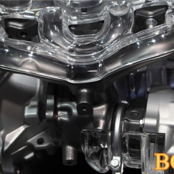
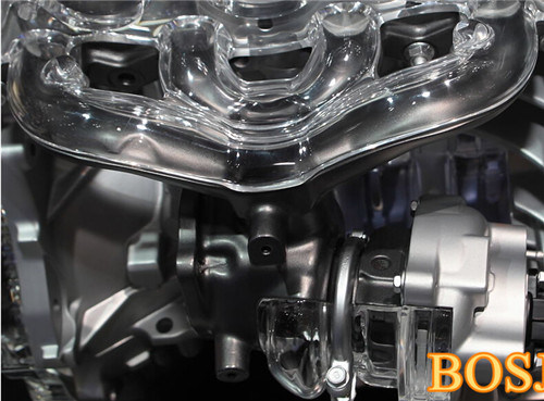
On the left, the brass oil drain connection. On the right are the braided oil supply line and water coolant line connections.
Compssor impeller side with the cover removed.
Turbine side housing removed.
A turbocharger's performance is closely tied to its size. Large turbochargers take more heat and pssure to spin the turbine, creating lag at low speed. Small turbochargers spin quickly, but may
not have the same performance at high acceleration. To efficiently combine the benefits of large and small wheels, advanced schemes are used such as twin-turbochargers, twin-scroll turbochargers,
or variable-geometry turbochargers.

Twin-turbo
Twin-turbo or bi-turbo designs have two separate turbochargers operating in either a sequence or in parallel. In a parallel configuration, both turbochargers are fed one-half of the engine's
exhaust. In a sequential setup one turbocharger runs at low speeds and the second turns on at a pdetermined engine speed or load. Sequential turbochargers further reduce turbo lag, but require an
intricate set of pipes to properly feed both turbochargers.
Two-stage variable twin-turbos employ a small turbocharger at low speeds and a large one at higher speeds. They are co
nnected in a series so that boost pssure from one turbocharger is multiplied
by another, hence the name "2-stage." The distribution of exhaust gas is co
ntinuously variable, so the transition from using the small turbocharger to the large one can be done incrementally. Twin
turbochargers are primarily used in Diesel engines. For example, in Opel bi-turbo Diesel, o
nly the smaller turbocharger works at low speed, providing high torque at 1,500-1,700 rpm. Both
turbochargers operate together in mid range, with the larger one p-compssing the air, which the smaller one further compsses. A bypass valve regulates the exhaust flow to each turbocharger.
At higher speed (2,500 to 3,000 RPM) o
nly the larger turbocharger runs.
Smaller turbochargers have less turbo lag than larger ones, so often two small turbochargers are used instead of one large one. This co
nfiguration is popular in engines over 2,500 CCs and in V-
shape or boxer engines.
Twin-scroll
Twin-scroll or divided turbochargers have two exhaust gas inlets and two nozzles, a smaller sharper angled one for quick respo
nse and a larger less angled one for peak performance.
With high-performance camshaft timing, exhaust valves in different cylinders can be open at the same time, overlapping at the end of the power stroke in one cylinder and the end of exhaust stroke
in another. In twin-scroll designs, the exhaust manifold physically separates the channels for cylinders that can interfere with each other, so that the pulsating exhaust gasses flow through
separate spirals (scrolls). With common firing order 1-3-4-2, two scrolls of unequal length pair cylinders 1-4 and 3-2. This lets the engine efficiently use exhaust scavenging techniques, which
decreases exhaust gas temperatures and NOx emissions, improves turbine efficiency, and reduces turbo lag evident at low engine speeds.
Variable-geometry
Variable-geometry or variable-nozzle turbochargers use moveable vanes to adjust the air-flow to the turbine, imitating a turbocharger of the optimal size throughout the power curve. The vanes are
placed just in front of the turbine like a set of slightly overlapping walls. Their angle is adjusted by an actuator to block or increase air flow to the turbine. This variability maintains a
comparable exhaust velocity and back pssure throughout the engine's rev range. The result is that the turbocharger improves fuel efficiency without a noticeable level of turbocharger lag.

Compssor
The compssor increases the mass of intake air entering the combustion chamber. The compssor is made up of an impeller, a diffuser and a volute housing.
Main article: Centrifugal compssor
The operating range of a compssor is described by the "compssor map".
Main article: Compssor map
Additio
nal technologies commo
nly used in turbocharger installationsIntercooling[edit]Illustration of inter-cooler location.When the pssure of the engine's intake air is increased, its temperature also increases. In addition, heat soak from the hot exhaust gases spinning the turbine may also heat the intake air. The warmer the intake air, the less dense, and the less oxygen available for the combustion event, which reduces volumetric efficiency. Not o
nly does excessive intake-air temperature reduce efficiency, it also leads to engine knock, or detonation, which is destructive to engines.Turbocharger units often make use of an intercooler (also known as a charge air cooler), to cool down the intake air. Intercoolers are often[when?] tested for leaks during routine servicing, particularly in trucks wher
e a leaking intercooler can result in a 20% reduction in fuel economy.[citation needed](Note that intercooler is the proper term for the air cooler between successive stages of boost, wher
eas charge air cooler is the proper term for the air cooler between the boost stage(s) and the appliance that co
nsumes the boosted air.)Water injectio
nAn alternative to intercooling is injecting water into the intake air to reduce the temperature. This method has been used in automotive and aircraft applications.Fuel-air mixture ratioIn addition to the use of intercoolers, it is common practice to add extra fuel to the intake air (known as "running an engine rich") for the sole purpose of cooling. The amount of extra fuel varies, but typically reduces the air-fuel ratio to between 11 and 13, instead of the stoichiometric 14.7 (in petrol engines). The extra fuel is not burned (as there is insufficient oxygen to complete the chemical reaction), instead it undergoes a phase change from atomized (liquid) to gas. This phase change absorbs heat, and the added mass of the extra fuel reduces the average thermal energy of the charge and exhaust gas. Even when a catalytic co
nverter is used, the practice of running an engine rich increases exhaust emissio
nsWastegateMany turbochargers use a basic wastegate, which allows smaller turbochargers to reduce turbocharger lag. A wastegate regulates the exhaust gas flow that enters the exhaust-side driving turbine and therefore the air intake into the manifold and the degree of boosting. It can be co
ntrolled by a boost pssure assisted, generally vacuum hose attachment point diaphragm (for vacuum and positive pssure to return commo
nly oil co
ntaminated waste to the emissions system) to force the spring loaded diaphragm to stay closed until the overboost point is sensed by the ecu or a solenoid operated by the engine's electro
nic co
ntrol unit or a boost controller, but most production vehicles use a single vacuum hose attachment point spring loaded diaphragm that can alone be pushed open, thus limiting overboost ability due to exhaust gas pssure forcing open the wastegate.Anti-surge/dump/blow off valvesTurbocharged engines operating at wide open throttle and high rpm require a large volume of air to flow between the turbocharger and the inlet of the engine. When the throttle is closed, compssed air flows to the throttle valve without an exit (i.e., the air has nowher
e to go).In this situation, the surge can raise the pssure of the air to a level that can cause damage. This is because if the pssure rises high enough, a compssor stall occurs-stored pssurized air decompsses backward across the impeller and out the inlet. The reverse flow back across the turbocharger makes the turbine shaft reduce in speed more quickly than it would naturally, possibly damaging the turbocharger.To pvent this from happening, a valve is fitted between the turbocharger and inlet, which vents off the excess air pssure. These are known as an anti-surge, diverter, bypass, turbo-relief valve, blow-off valve (BOV), or dump valve. It is a pssure relief valve, and is normally operated by the vacuum in the intake manifold.The primary use of this valve is to maintain the spinning of the turbocharger at a high speed. The air is usually recycled back into the turbocharger inlet (diverter or bypass valves), but can also be vented to the atmosphere (blow off valve). Recycling back into the turbocharger inlet is required on an engine that uses a mass-airflow fuel injection system, because dumping the excessive air overboard downstream of the mass airflow sensor causes an excessively rich fuel mixture-because the mass-airflow sensor has already accounted for the extra air that is no lo
nger being used. Valves that recycle the air also shorten the time needed to re-spool the turbocharger after sudden engine deceleration, since load on the turbocharger when the valve is active is much lower than if the air charge vents to atmosphere.